Description
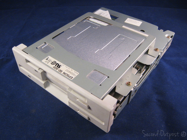
This is a used Epson SD 800/700 Dual 3.5″ & 5.25″ Internal Floppy Disk Drive in good working condition. This is a Beige Front Panel model.
EPSON SD-800/700 DUAL FLOPPY DISK DRIVE
INSTALLATION INFORMATION & SPECIFICATIONS
The EPSON SD-800/700 is a dual floppy disk drive. This will guide you through the installation of the floppy disk drive (FDD) into your computer. The EPSON SD-800/700 FDD is compatible with all IBM PC compatible computers. This FDD uses the industry standard ISA interface which assures you of industry-wide compatibility.
NOTE: Make sure your computer BIOS Supports 2 floppy drives! Most modern computers only support a single floppy drive.
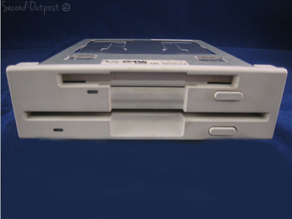
This FDD conveniently combines a 3.5″, 1.44 Megabyte floppy disk drive with a 5.25″, 1.2 Megabyte floppy disk drive in a half-height chassis. With a single interface connector this FDD can be installed in either the upper slot or lower slot in your PC. With one jumper, the 3.5″ FDD can be configured for the ‘A’ or ‘B’ drive or the 5.25″ FDD can be configured to be the ‘A’ or ‘B’ drive, the choice is yours.
How to install the EPSON SD-800/700 dual FDD into your computer:
First turn off the computer and remove the power cable. Dangerous AC and DC voltages are used within the computer case when the computer is turned on and plugged in.
Please refer to your computer manual to determine the correct method to open your computer case and to gain access to the FDD slots in the front of the case.
Install the EPSON SD-800/700 FDD in either the upper or lower FDD slot in your PC. The FDD is mounted using four screws, two on each side. It may be necessary to repeat this procedure until the bezel of the FDD mounts flush to the front of the PC.
The FDD can be configured 4 different ways depending on the FDD connector used and the position of the SS1 jumper on the FDD. There are 2 jumper blocks accessible from the top side of the SD-800/700 dual floppy disk drive. For most applications, no changes are required in the jumper blocks. If a change is determined necessary, make sure that the computer is off and unplugged.
Please refer to the diagram below for more information:
| 3.5″ | 5.25″ | ||||
| Slot | Connector | SS1 | (1.44Mb) | (1.2Mb) | |
| Configuration 1: | Upper | Drive A | A | A | B |
| Configuration 2: | Upper | Drive A | B | B | A |
| Configuration 3: | Lower | Drive B | A | B | A |
| Configuration 4: | Lower | Drive B | H | A | B |
FDD cable (inside PC) 34-pin Drive B 34-pin Drive A
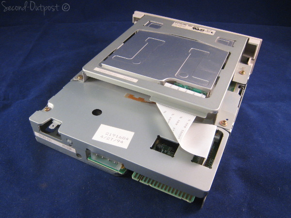
Attach the 4-pin power cable to the rear of the FDD and attach the 34-pin edge connector to the rear of the FDD. When looking at the rear of the FDD, pin 1 of the connector is to the left. There is a small slot between pins 4 and 6 on the FDD connector, line up the cable connector with this slot.
Jumper Configurations
| A | 1 | 3 | D | L | R | ||
|
|
|
||||||
| X | O | O | O | O | O | ||
| SS1 | X | SS2 | O | O | X | X | O |
| O | O | O | X | X | O | ||
|
|
|
||||||
| B | 0 | 2 | S | H | D | ||
| Default Jumper Settings | |||||||
Jumper Definitions
| Drive Select: | |
| SS 1 | Drive Configuration |
| A | Drive Select A = 5.25 |
| Drive Select B = 3.5″ | |
| B | Drive Select A = 3.5″ |
| Drive Select B = 5.25 |
Mode Change (5.25″):
| SS 2 | Logic |
| L | Low: HIGH mode |
| High: NORM mode | |
| H | Low: NORM mode |
| High: HIGH mode |
Motor Speed in NORM mode (5.25″):
| SS 2 | Speed |
| D | 300 RPM |
| S | 360 RPM |
Do not place jumpers on SS2, pins 0, 1, 2, 3, R, or D.
SS1 Determines the “drive select” for the 3.5″ and 5.25″ FDD. In the default position (A) the *A* drive is the 3.5″ FDD **if** the dual drive is in the upper slot of the pc and uses the FDD connector on the end of the cable (after the “twist”).
If the SS1 jumper is changed to the (B) position, the 5.25″ FDD becomes the *A* drive **if** the dual drive is in the upper slot of the PC and uses the FDD Connector on the end of the cable (after the “twist”).
SS2 No jumpers are necessary between the 0-1-2-3 jumpers. The D-S jumper determines the rotational speed of the 5.25″ FDD. The default position (S) sets the speed to 360RPM. The (D) position sets the speed to 300RPM.
The L-H jumper determines the mode of the 5.25″ FDD. The default position (H) defines Low as Norm mode and High = High mode.
Note: Most PC’s can **only** access two FDDS. The SD-800/700 takes the place of 2 FDDS.
Replace the cover of the computer and replace the power cable. Turn on the computer and verify the CMOS settings on the computer by running your SETUP program which came with your computer. Be sure to inform the SETUP program of the configuration you have selected for the new dual FDD.
Specifications:
Size:
Height: 41.5mm
Width: 148mm
Depth: 192mm
Weight: 1100g
3.5- FDD:
Recording method (MFM): High Density Standard Density
Capacity (Unformatted): 2.0 1.0 MB
Capacity (Formatted): 1.4740.737 MB
Transfer rate: 500 250 KBit / Sec
Maximum recording density: 17,434 8,717 BPI
Track density: 135 TPI
Number of tracks (2 sided): 160
Disk rotation: 300 rpm (typ)
Seek time (trk to trk): 3 ms
Settling time: 15 ms
Average time for seeking: 95 ms
Motor start time: 500 ms
Average latency: 100 ms
5.25- FDD:
Recording method (MFM): High Mode Standard Mode
Capacity (Unformatted): 1.667 1.0 MB
Capacity (Formatted): 1.229 0.737 MB
Transter rate: 500 300K Bit / sec
Maximum recording density: (tk79) 9,870 5,922 BPI
Track density: 96 TPI
Number of tracks (2 sided): 160
Disk rotation: 360 rpm (Typ)
Seek time (trk to trk): 3 ms
Settling time: 15 ms
Motor start time: 500 ms
Average latency: 83 ms
EPSON is a registered trademark of Seiko Epson Corporation.